 There are a lot of ways to construct a remote controlled airplane. Different kits are available for designing a RC plane. Cost and performance of RC plane is depend on the way of construction. Normally kits are made of foam or plastic or balsa wood. For the construction of fuselage formers and longerons are used. For wings and tail surfaces normally spars and ribs are used. Solid sheets of wood also sometimes used for structure construction. For heavy RC airplane construction a composite wing consisting of expanded polystyrene core covered by the safety veneer of wood is used. If we want to make remote controlled airplane for windless environment, the lightest models are most preferable.
 Sunday, November 13, 2011
Construction of Remote Controlled Airplane
 There are a lot of ways to construct a remote controlled airplane. Different kits are available for designing a RC plane. Cost and performance of RC plane is depend on the way of construction. Normally kits are made of foam or plastic or balsa wood. For the construction of fuselage formers and longerons are used. For wings and tail surfaces normally spars and ribs are used. Solid sheets of wood also sometimes used for structure construction. For heavy RC airplane construction a composite wing consisting of expanded polystyrene core covered by the safety veneer of wood is used. If we want to make remote controlled airplane for windless environment, the lightest models are most preferable.
 Types of Remote Controlled Airplane
 Although all the aviation airplanes models are not possible to build in realistic but the scientists are using aeromodeling to give it a possible replicate full-scale aircraft model. Its main purpose is to test the future aviation designs, to realize the limitaions of making a proposed aircraft. Normally remote controlled aircrafts are lighter (even lighter than the air) than the aviation aircrafts. It can also make as the heavier than the air (wing glider/sail plane), fixed-wing single or multiple, multiple engine or rotary wing aircraft (autogyros/ helicopters).
The most interesting thing for remote controlled airplanes builders is that they are capable of making a controllable mini aircraft that almost look like full scale original aircraft. For desigining a full scale aircraft one need to consider about detailed cockpit, operable cable connected flight control surfaces, fixing landing gear etc. But these need not to be considered as making remote controlled airplane.
Remote Controlled Airplanes
A remote controlled airplanes or RC Plane is controlled remotely by a hand-made transmitter and a receiver within the aircraft. The main use of the receiver is to adjust controls of the corresponding servos (a small device that has a three phase DC motor, a gear, an IC or Integrated Circuit, a potentiometer and a shaft bearing) that run the control surfaces depend on the position of joysticks of the transmitter. Flying remote control aircraft has become a hobby of the worldwide people. There is a wide variety of models and styles are available for RC planes. Experiments and researches are made nowadays for using more efficient motors, low cost maintenance more fuel efficient internal combustion or jet engines, lighter and more effective batteries and more powerful radio systems. The most important thing is that scientific, military, government and non government organizations are trying to use remote control airplanes for experiments, defense system, weather forecasting and even use these RC planes as spy planes or drones.
Thursday, September 29, 2011
Deflection Yoke
Deflection Yoke - pictured below, wraps around the neck on the CRT and extends partway up along the sloped sides. The yoke has signals running through it's wires that create a strong electrical/magnetic field - rapidly deflecting the electron beam, scanning across the screen to paint full frames at a rate of 60 frames per second. The entire concept is truly amazing.
Fly Back Transformer
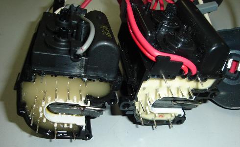
The fly back transformer is an important component for the horizontal section. It is also known as the horizontal output transformer (HOT). It is an auto transformer having multi windings. So it is also a multi winding transformer.
Working Principle of CRT
The electrons emitted from the cathode makes an electron cloud. This electron cloud then forms the electron beam. This electron beam then with the help of the yoke or the combined horizontal and vertical scanning coil moves left-right and up-down. By this process the beam hit the screen of the CRT. As the CRT has many dots which are light sensitive and coated with the phosphors. The phosphor chemicals are light metals as Zinc (Zn) and Cadmium (Cd) in the form of Sulphide, Sulphate and Phosphate compounds.
Construction Details of CRT
1) Electron gun:
It is very simple device which mainly produces thin electron beam. It is the combination of Heater, Cathode and the Grids. All this components are situated at the base of the tube. The heater heats the cathode and then the cathode emits a lot of electrons which make an electron cloud. The electron gun is analogous to the pen. In different parts of the electron gun different types of voltages are required. These voltages vary within the range 200-600 Volts. The electron gun receives voltages from the receiver which is connected with the base pins of the CRT.
2) Heater:
The heater is mainly used to heat the cathode. It is made of metals and twisted in shape. It heats the cathode indirectly. It needs 6-24 Volts dc or ac supply voltage.
Wednesday, September 28, 2011
Cathode Ray Tube
The Cathode Ray Tube is an optoelectronic device. That is it converts electrical signal into video signal. Physically it is a large, hard and evacuated glass tube.
In most optical devices, it posses most of the places. Actually it is the heart of an oscilloscope and is very similar to the picture tube of Television Set, Computer Monitor etc. with a view to saving space in TV set it is designed with a narrow neck and a large deflection angle. In the narrow neck it contains most of the important components for processing the signal. The tubes are usually designated by the maximum deflection angle and the length along the diagonal of the screen.
CRT has two main parts.
1) Base/Low voltage side (<1 KV)
2) Anode/High voltage side (> several KV)
The base or low voltage side also contains the following parts:
1) Electron Gun
2) Heater
3) Cathode
4) Grids
Tuesday, September 27, 2011
Scanning Coils of Television
Actually the main duty of the video section is to scan the picture on the screen so that the viewers can watch them. For this only purpose the vast arrangement is needed. The scanning coil is the most important component for the video section. It is located on the base of the CRT. The electron beam produced by the electron gun is finally directed by the scanning coil with different frequencies. The scanning coil is nothing but just a device to produce magnetic field. This magnetic field deflects the electron beam to and fro. We know that the scanning process is analogous to writing on the paper with a pen. That is, it needs to go first towards horizontally and then vertically. For these purposes there need two different coils. One is horizontal scanning coil and another is vertical scanning coil. These two coils are named as ‘Yoke’ together. This yoke is fixed outside the tube and close to the neck of the tube just before it begins to flare out. For two different types scanning there need two different types of scanning coil. One is the horizontal and another is the vertical scanning coil.
Horizontal Section of Television
In television there are some important sections.Among these sections horizontal and vertical section are one of the main sections.Horizontal Section consists of the following parts:
1.Horizontal oscillator
2.Horizontal sweep control
3.Driver transistor
4.Driver transformer
6.Horizontal Output Transistor
Monday, September 26, 2011
Troubles on the Stabilizer Section
There are different types of troubles occurs due to fault in the power supply section. Some of them are given below:
1. No B+ Voltage:
Troubles that can cause no B+ voltage include an open diode in rectifier circuit, an open filter choke or resistor and shorted filter capacitor. The capacitor becomes open or practically open with reduced capacitance. As a result the poor regulation of the B+ voltage for the load & excessive hum.
2. Blooming:
This term describes a picture that increases in size, defocusing in white areas as the brightness is increased. A common cause of blooming is a weak high voltage rectifier, which has excessive internal resistance.
Main Sections of Television
DIFFERENT SECTIONS OF B & W TV MODEL PHILIPS E1-CCIR
• STABILIZER SECTION
• HORIZONTAL SECTION
• VERTICAL SECTION
• VIDEO SECTION
• SOUND SECTION
UNIT BLOCK DIAGRAM OF STABILIZER SECTION (SBS):
Sunday, September 25, 2011
Television
Television is an electronic system for conveying pictures from one place to another. It is almost an extension of the human eye in modern life, in countries with extensive TV network. The basic technique of converting an optical signals, sending over wires or through space and receiving them to reproduce the image on a screen.
Saturday, September 24, 2011
Television Engineering
Main Features
•Introduction
•Unit block diagram of B & W TV
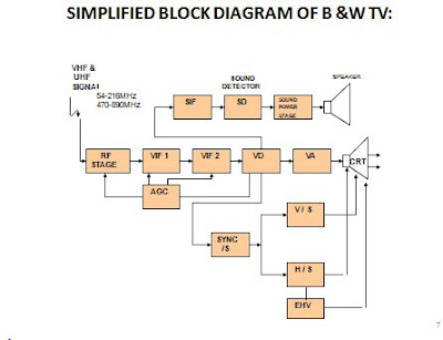
•Simplified block diagram of B & W TV
•Complete Block Diagram Of B & W Receiver
•Complete schematic diagram of B & W TV
•Pictorial Diagram Of B & W TV
•Different Sections of B & W TV Model Philips E1-CCIR
•Unit block diagram of stabilizer section (SBS)
•Stage & Complete block diagram of stabilizer section (SBS)
•Schematic diagram of stabilizer section (SBS)
Subscribe to:
Comments (Atom)


